
For a PDF of this paper click here.
BIOGRAPHY
Tim Eadie (B.Sc. Eng.) graduated in geomatics engineering from York University in Toronto in 2008. He worked as a geophysicist in quality control data processing for Quantec Geoscience from 2006 until 2010 when he joined Geotech Ltd. He is senior geophysicist and research engineer who is mainly interested in helicopter time-domain electromagnetic data processing and modelling. Jean M. Legault (M.Sc.A.) is chief geophysicist, Geoffrey Plastow (B.Sc) is data processing manager, and Dr. Alexander Prikhodko (PhD) is director of geophysics at Geotech.
SUMMARY
Several design improvements to VTEM-ET have: increased the receiver bandwidth, allowing for measurements as early as 5µs after the end of the waveform pulse. The VTEM ET system features a redesigned, transmitter, improved current waveform with faster current turn-off, a new broadband receiver and new digital acquisition system with faster, ~1 microsecond sampling. These enhancement have improved VTEM-ET’s sensitivity to changes in near-surface geology and our ability to resolve these changes more accurately through modelling. This has been demonstrated by comparing the performance of VTEM-ET to VTEM Plus through the generation of synthetic forward data and their inversion using the GALEISBSTDEM code. Results show that VTEM-ET has greater sensitivity to more subtle changes in the resistivity and thickness of individual geological layers in comparison to VTEM Plus, as well as improved. The two systems are compared using real-world data collected over a portion of the Spiritwood aquifer in North Dakota that has good well log lithological control. 1D inversion of both sets of field data appears to confirm that VTEM-ET more accurately defines the main geological layer boundaries relative to VTEM Plus in the upper 50-100m. This improved accuracy is due to the greater sensitivity of VTEM-ET from each of the design improvements to the system.
INTRODUCTION
Sampling the earliest possible transient EM decay in time-domain airborne electromagnetic data (TDEM) is critical for shallow near surface applications. As part of a continued system design strategy aimed at expanding its early-time VTEMTM (versatile time-domain electromagnetic; Witherly et al., 2004) data range, the latest evolution of the system, VTEM ET (Figure 1) or Early Time (Legault et al., 2017b) focuses on further improving the system’s capabilities for near surface applications, such as groundwater and environmental.
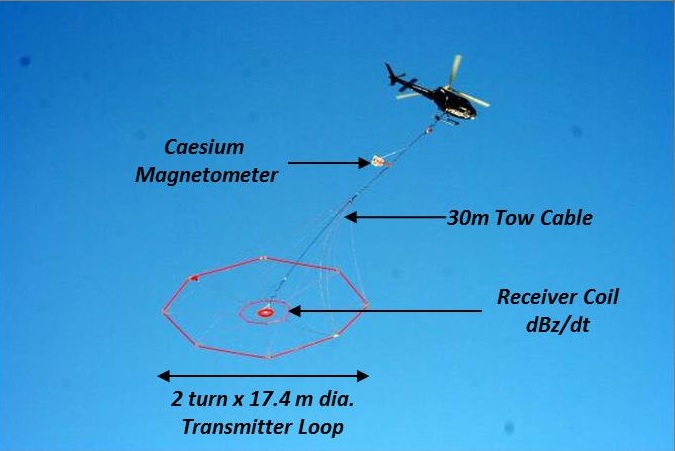
Figure 1. VTEM ET helicopter time-domain EM system.
The VTEM ET system improvements include: a) increased receiver bandwidth, b) microsecond resolution of early time channel measurements, and c) shorter transmitter current waveform turn-off. Each of these improvements contributes to an overall increase in the system’s sensitivity to subtle changes in the near-surface geology and improves the accuracy of data models. The results are precise, distortion free measurements of the time-domain EM decay as early as 0.005 ms after the transmitter turn-off. This is initially demonstrated in our paper using synthetic forward and inversion modelling of VTEM ET data compared to VTEM Plus. To further demonstrate VTEM ET’s increased sensitivity, inversion results from the Spiritwood aquifer region of North Dakota (Legault et al., 2017a) are compared against well log lithology.
System Description
The VTEM ET system is comprised of a 17.4 metre diameter transmitter loop with 2 turns (Fig. 1). This allows it to reduce the turn-off time of the waveform to less than 500µs which is 3 times faster than previous VTEM systems (~1.5 ms). The faster turn-off of the waveform generates a stronger ground response and results in larger signal amplitudes measured by the receiver and enhances the signal-to-noise. As with other VTEM systems, the system’s versatility allows its configuration to be optimized to meet the project’s objectives. For example, VTEM ET can reach a peak current and dipole moment of 330 A and 157,080 NIA, respectively, using a 4 ms long waveform pulse (Fig. 2) that allows longer off-time decay measurements (15.4 ms) in conductive environments; or 230 A and 109,480 NIA with a 7 ms long waveform pulse for maximum primary field saturation and improved signal to noise.
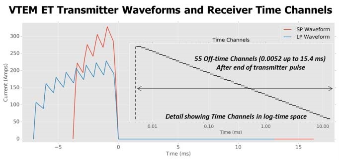
Figure 2. VTEM ET transmitter waveforms (4 ms and 7 ms pulse widths) and off-time receiver channel positions (inset).
VTEM ET employs an improved receiver design with increased bandwidth that permits time channel measurements as early as 5µs after the end of the waveform pulse. This is an improvement of 13µs over the earliest time channel from VTEM Plus. By measuring data closer to the end of the end of the waveform, VTEM ET is more sensitive to the geology in the first tens of metres. It is able to extract resistivity information contained in the first tens of microseconds which will improve the overall quality of the data model.
In conjunction with an increased receiver bandwidth, VTEM ET records fully streamed data at a sample rate of 864,000 samples per second and allows it to obtain microsecond resolution between time channels for the earliest portion of the ground’s signal decay which is steepest. The dense sampling of this portion of the decay enables VTEM ET to detect more subtle variations in the very near-surface geology resulting in better resolution for the system.
VTEM ET SYSTEM TESTING
1D Forward Modelling and Inversion
1D forward modelling is used to predict the ground responses from various systems and demonstrates the effect that the design improvements to VTEM ET have on the measured data. A two-layer modelling scenarios is used to illustrate how those model changes affect the predicted response between VTEM ET and VTEM Plus. The predicted responses were then inverted to show how accurately the initial models could be recovered. The modelling used the Geoscience Australia GALEISBSTDEM (https://githum.com/Geoscience Australia/ga-aem; Ley-Cooper, 2016) 1D layered earth inversion code. Both systems were modelled using the VTEM ET 7 ms pulse waveform (blue curve in Fig. 2).
The modelling scenario in Figure 3 is a simple two layer model, with the first layer being more resistive than the second basement layer and is shown with the black line in the model pane. The model pane contains three additional models that vary from the first model by: the first layer’s resistivity (red), first layer’s thickness (green), and second layer’s resistivity (blue). The forward modelled responses of VTEM ET and VTEM Plus for each of the models are shown in the middle pane of Figure 3. As shown, each of the changes in the model (Fig. 3a) creates a change in the response for both systems (Fig. 3bc). When comparing the response of VTEM ET and VTEM Plus, it is clear that the VTEM ET amplitudes are much greater, particularly in the earliest time channels. This higher amplitude decays for VTEM ET are due to the shorter transmitter turn-off that enhances the signal-to-noise of the data.
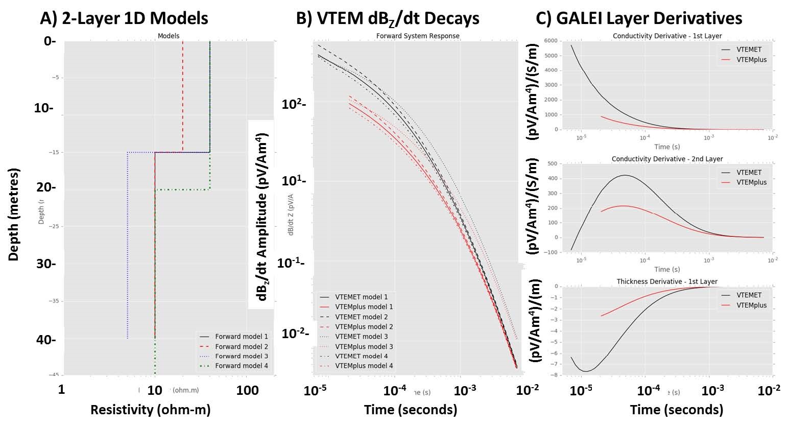
Figure 3. 1D Forward Modelling: 2-layer case: A) Four (4) 1D model scenarios, B) Off-time dBZ/dt EM decays for VTEM ET (black curves) and VTEM Plus (red); C) Derivative curves for each layer-parameter for VTEM ET (black) and VTEM Plus (red).
The changes in the model responses for the various model scenarios can be expressed through the conductivity and thickness derivatives that were derived using the GALEISBSTDEM code and are presented in Figure 3c. The derivative plots show the relative amplitude change with respect to time. By comparing each of the derivative plots, it’s clear that there is always a greater amplitude change in the response for VTEM ET relative to VTEM Plus, especially in the earliest time channels. This suggests that VTEM ET is more sensitive to smaller changes in the near surface conductivity and thickness of the models relative to VTEM Plus.
Next, the forward model responses for VTEM ET and VTEM Plus were inverted using the GALEISBSTDEM code. For the inversions, each of the synthetic data was assigned an appropriate error level based on previous experience inverting real data. The inversions were constrained to the same number of layers as the reference models (two). From the results shown in Figure 4a-d for each model from our 2-layer modelling scenarios, the inversions are generally more effective at recovering the reference model for VTEM ET than VTEM Plus, except in the case for model 3 (Fig 4c), where they are very similar. These and other modelling results have shown how improvements to VTEM ET result in its being more sensitive to subtle change in near-surface geology, as well as improved accuracy during inversion modelling.
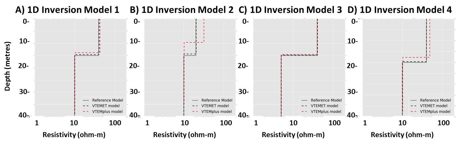
Figure 4. 1D LEI inversion of forward Modelling from Figure 2: A) Model 1, B) Model 2, C) Model 3 and D) Model 4, for VTEM ET (black curve) and VTEM Plus (red).
North Dakota Test Example
To demonstrate the VTEM ET system improvements, data were collected with both the VTEM ET and VTEM Plus over the Spiritwood glacial aquifer in North Dakota (Legault et al., 2017ab). Figure 5 presents a plan view of VTEM ET dBZ/dt late-channel off-time results over the test area, highlighting the main Spiritwood channel aquifer that has a NNE-SSW trend, as well as a previously unknown secondary aquifer of interest that is NW-SE trending and crosscuts the main Spiritwood aquifer. Figure 6 presents a resistivity cross-section along L2300 (see Fig. 5), consisting of stitched 1D models using the GALEISBSTDEM code, that illustrates the lateral continuity of multiple layers in the upper 50-100m that are resolved in the VTEM ET results, as well as the main Spiritwood and the secondary aquifer that form resistive channels in the incised Cretaceous shale basement rocks. This interesting test area presented a useful setting to test the abilities of VTEM ET in a stratified environment along with publicly available well log data for comparison.
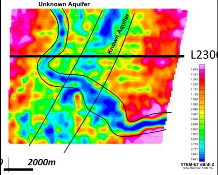
Figure 5. VTEM ET mid-late channel (1.80 msec.) off-time dBZ/dt decay amplitude, with location of L2300 shown in Fig. 6.
Figure 7 presents unconstrained 10-layer inversions using the GALEISBSTDEM code for two locations along with the well log lithology. From the various lithological units, we can infer that shale are the most conductive (2-5 ohm-m), followed by silt and till (15-30 ohm-m), the sand and gravel that are the most resistive (30-50 ohm-m). When comparing the unconstrained inversion model results to the well log lithology, both systems appear to be relatively effective at resolving these main lithological units. However, compared in greater detail, the VTEM ET models appear more accurate at defining the depths to the boundaries that represent the main resistivity contrasts, in particular the top of the shale. For both of the stations, the VTEM ET model more accurately defines this boundary, whereas the VTEM Plus models appear to over-estimate its depth. The VTEM ET models also appear to more accurately define the till/silt and sand/gravel boundaries.
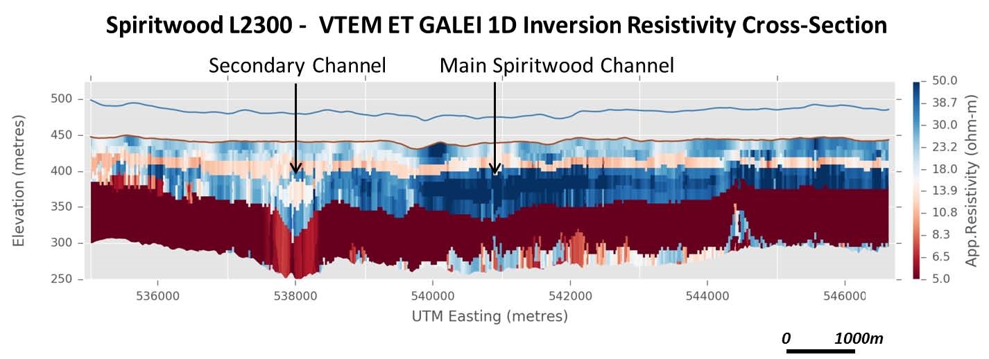
Figure 6. Resistivity-depth cross-section for L2300 (see Fig. 5) from Spiritwood Valley VTEM ET test survey.
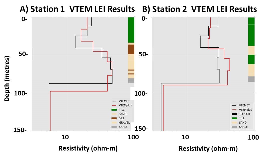
Figure 7. Spiritwood Aquifer VTEM 1D inversion results and borehole lithology: A) Station 1, and B) Station 2, for VTEM ET (black curve) and VTEM Plus (red).
CONCLUSIONS
Design improvements in the VTEM ET system have increased the receiver bandwidth allowing for measurements as early as 5µs after the end of the waveform pulse, result in microsecond resolution for early time channel measurements due to the system’s increased sampling rate, and shortened the waveform’s turn-off time, thus increasing the EM decay amplitudes relative to previous VTEM system. These have enhanced VTEM ET’s sensitivity to changes in near-surface geology and its ability to resolve these changes more accurately through modelling. This has been demonstrated by comparing the performance of VTEM ET to VTEM Plus using synthetic 1D forward modelling and inversion. The two systems were also compared over a portion of the Spiritwood aquifer in North Dakota with well log lithological data. These results also showed that VTEM ET was more accurate at defining the depths of main geological boundaries that represent distinct resistivity contrasts.
REFERENCES
Legault, J.M., Eadie, T., Plastow, G., and Prikhodko, A. [2017a] Spiritwood valley aquifer characterization using a helicopter TDEM system. National Groundwater Association, conference on hydrogeophysics and deep groundwater, NGWA, conference abstract, 1 p.
Legault, J.M., Eadie, T., Plastow, G., Prikhodko, A. and Tishin, P. [2017b] An improved helicopter time-domain EM system for groundwater and environmental applications. 30TH SAGEEP symposium on the application of geophysics to engineering and environmental problems, EEGS, conference abstract, 1 p.
Ley-Cooper, A.Y. [2016] Dealing with uncertainty in AEM models (and learning to live with it). 25TH International Geophysical Conference and Exhibition, ASEG, Extended Abstracts, 713-718.
Witherly, K., R. Irvine, and E.B. Morrison [2004] The Geotech VTEM time domain electromagnetic system. 74TH Annual Meeting and International Exposition, SEG, Expanded Abstracts, p. 1217–1221.