For a PDF of this paper click here
Introduction
Introducing the Full Waveform VTEM™ system, the most recent technological development by Geotech, designed to achieve fully calibrated time-domain EM decays for better near-surface mapping than was previously possible with earlier VTEM™ systems. The new VTEM™ design uses the streamed half-cycle recording of transmitter and receiver waveforms to obtain a complete system response calibration throughout the entire survey flight that helps to precisely eliminate the effect of the data acquisition system response on the recorded signals. The full waveform technology can be added to the standard VTEM™ system without diminishing its patented and industry leading low noise and deep penetration characteristics.
In addition to improving the system bandwidth and the complete system response calibration, newly developed digital signal processing techniques have been applied that are aimed at reducing the effect of the input transmitter waveform and time-varying injected current using both a parasitic loop capacitance correction and a transmitter drift correction, as well as ideal waveform deconvolution. These implementations have helped improve the accuracy of the measured earth-response particularly in the earliest portions of the off-time EM decay – considerably close to the transmitter current turn-off than the 100us limit allowed for by previous VTEM™ systems.
Results of the full waveform VTEM™ helicopter system implementation over the Spiritwood Valley aquifer, in southern Manitoba (Fig. 1a), have shown a significant improvement in quantitative VTEM™ data at earlier times than previously achieved – allowing up to 45 time-gait measurements, from 0.018 to 9.286ms (ch4-47) after the current turn-off. This has resulted in improvements in the model space that include better definition of the near-surface heterogeneity and also a more compact resistive anomaly associated with the buried valley aquifer that is in good agreement with previous seismic and resistivity results, the most recent technological development by Geotech, designed to achieve fully calibrated time-domain EM decays for better near-surface mapping than was previously possible with earlier VTEM™ systems. The new VTEM™ design uses the streamed half-cycle recording of transmitter and receiver waveforms to obtain a complete system response calibration throughout the entire survey flight that helps to precisely eliminate the effect of the data acquisition system response on the recorded signals. The full waveform technology can be added to the standard VTEM™ system without diminishing its patented and industry leading low noise and deep penetration characteristics.
In addition to improving the system bandwidth and the complete system response calibration, newly developed digital signal processing techniques have been applied that are aimed at reducing the effect of the input transmitter waveform and time-varying injected current using both a parasitic loop capacitance correction and a transmitter drift correction, as well as ideal waveform deconvolution. These implementations have helped improve the accuracy of the measured earth-response particularly in the earliest portions of the off-time EM decay – considerably close to the transmitter current turn-off than the 100us limit allowed for by previous VTEM™ systems.
Results of the full waveform VTEM™ helicopter system implementation over the Spiritwood Valley aquifer, in southern Manitoba (Fig. 1a), have shown a significant improvement in quantitative VTEM™ data at earlier times than previously achieved – allowing up to 45 time-gait measurements, from 0.018 to 9.286ms (ch4-47) after the current turn-off. This has resulted in improvements in the model space that include better definition of the near-surface heterogeneity and also a more compact resistive anomaly associated with the buried valley aquifer that is in good agreement with previous seismic and resistivity results.
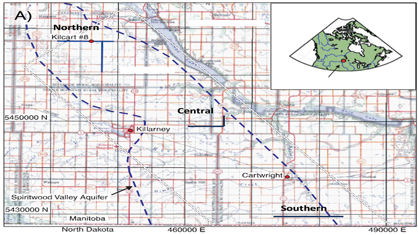
Figure 1a) Spiritwood Valley location, aquifer outline and VTEM™ survey test lines (modified after Oldenborger et al., 2010)
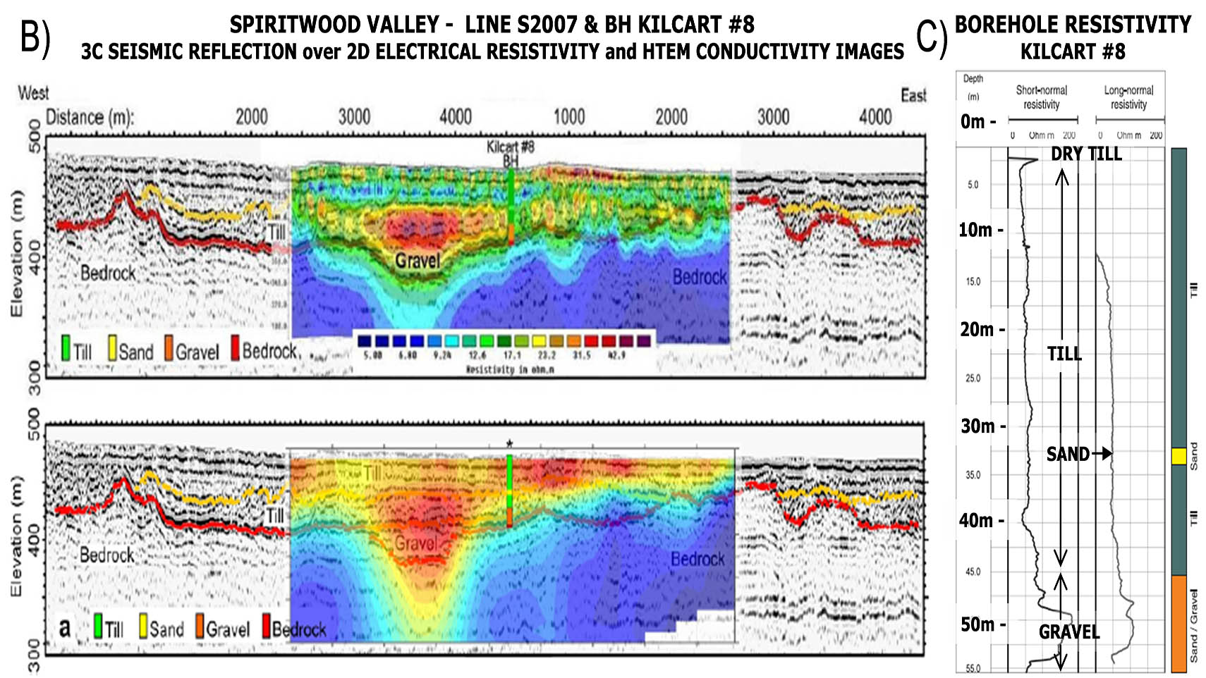
Figure 1b) Previous geophysics over northern test line (from Oldenborger et al., 2011); 1c) Long and short-normal resistivity log for Kilcart #8 (after Oldenborger et al., 2010).
Full Waveform Description
Full Waveform VTEM™ system was developed in late 2011 for improved early time data using standard VTEMPLUS (Fig. 2a) as well as VTEM early time systems. The significant features of the full waveform technology are: a) streamed half-cycle recording of transmitter and receiver waveform data, and, during the post-processing stage, b) continuous system response calibration, c) transmitter drift & parasitic noise correction, and d) ideal waveform deconvolution.
The sensor calibration procedure uses the measured calibration waveform for correction of half-cycle waveforms acquired on a survey flight. The half-cycle waveforms of each channel are corrected to obtain the waveforms that would be recorded if the time-domain responses of all the channels, including the reference channel, were the same ideal Gaussian-like response. The ideal response (Fig. 2b) is defined by its bandwidth.
A streamed current monitor and streamed receiver data are used for transmitter drift and parasitic noise corrections and ideal waveform deconvolution. The deconvolution procedure corrects one complete period for linear system imperfections including transmitter current drift through the following operation:
R(t) ó R(w) = [C0 (ω) B(ω) ] / [C0 (ω) H0 (ω) W(w)]
Where R(t) is the desired response (corresponding to R(w) in frequency domain), C is the instantaneous current monitor and C0 the averaged high altitude reference current monitor measurement, B the instantaneous survey data and H0 the averaged high-altitude data respectively. W(w) is an ideal waveform for which the response is desired (Macnae and Baron-Hay, 2010).
Spiritwood Valley Geology
To test the full waveform VTEM™ system implementation, the Spiritwood Valley was chosen as a test area based on the availability of previous airborne and ground EM, electrical and seismic, borehole geophysical and well-log data from the study of a shallow freshwater aquifer by the Geological Survey of Canada (Oldenborger et al., 2010 and 2011; Oldenborger, 2010a and 2010b). The Spiritwood Valley is a 10-15km wide, 100-150m deep, northwest-southeast trending, buried bedrock valley that extends between Killarney and Cartwright (Fig. 1a) and extends 500km from Manitoba, across North Dakota and into South Dakota.
The valley lies within a till plain with little topographic relief but has been defined by a series of borehole transects and seismic reflection data collected north of Killarney. The stratigraphy within the valley is variable but includes a basal, shaly sand and gravel, and overlying clay-rich and silty till units. But the sand and gravel is only found in incised valleys, making for a valley-within-valley morphology. The underlying bedrock is conductive, fractured silicious shale. According to borehole resistivity log results (Fig. 1c), the simplified electrical section consists of three main units: 1) till (40-50 Ω-m), 2) sand & gravel (70-200 Ω-m) and 3) shale bedrock (5-50 Ω-m). The high resistivity of the sand and gravel makes it a marker unit for the incised valleys that are groundwater targets (Oldenborger et al., 2010).
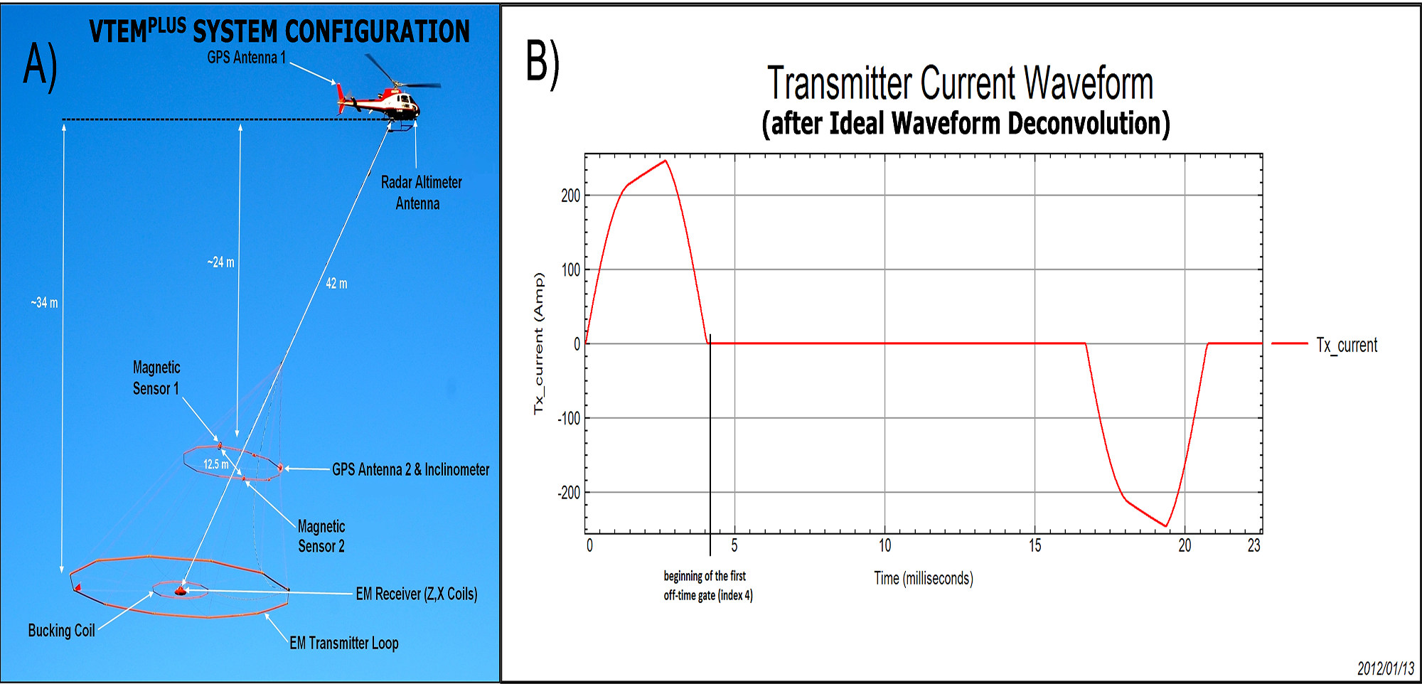
Figure 2a) VTEM plus helicopter EM system configuration; 2b) Transmitter current waveform (after ideal wave form deconvolution) at Spiritwood Valley.
Figure 1b shows an example of inverted resistivity models for ground electrical tomography (ERI) and AEM data acquired at the northern end of the survey area, and compares them to the 3C seismic reflection data. The resistivity results show the relatively higher resistivities associated with the deepest part of the valley, suggesting that these sediments are potential aquifer targets. Synthetic modelling of the inversion results shows that the channel anomaly is consistent with erosion of both a supra-bedrock layer (till) and bedrock. The results indicate that ERI provides superior spatial resolution, while the AEM has more limited dynamic range (Oldenborger et al., 2011).
Full Waveform VTEM™ Test Results
During Fall, 2011, Geotech conducted a helicopter-borne geophysical survey over the Spiritwood Valley test area that extends from approximately 20 km north to nearly 28km of Killarney, Manitoba. The survey was conducted across three separate reconnaissance test areas that matched ground seismic and ground resistivity survey work undertaken previously and consisted of three sets of east-west and 1 set of north south lines (Fig. 1a). Both the standard VTEM™ and VTEM™ early time systems were repeatedly flown over each set of lines, for a total of 217km surveyed.
The VTEM™ survey results were initially processed using standard methods, with the system calibration correction and the parasitic-noise/transmitter-drift/ideal-waveform-deconvolution corrections applied in a separate post-processing step using the full-waveform data. The VTEM™ data were then treated with 1D laterally constrained-inversions (LCI) using an in-house developed heuristic laterally constrained inversion (HLCI) that is based on the AirBeo layered earth 1D TEM inversion code (2007, CSIRO/AMIRA).
Results of the full waveform VTEM™ survey over the Spiritwood Valley aquifer have shown a significant improvement in quantitative VTEM™ data at earlier times than previously achieved – as early as 18 μs after the current turn-off. As shown in Figure 3 (showing LCI and seismic sections across northern and central survey lines), these include better definition of the surficial dry till layer and also a more compact resistive anomaly associated with the buried valley aquifer that is in good agreement with previous seismic and resistivity results, which is therefore likely to be significant for groundwater resource management purposes.
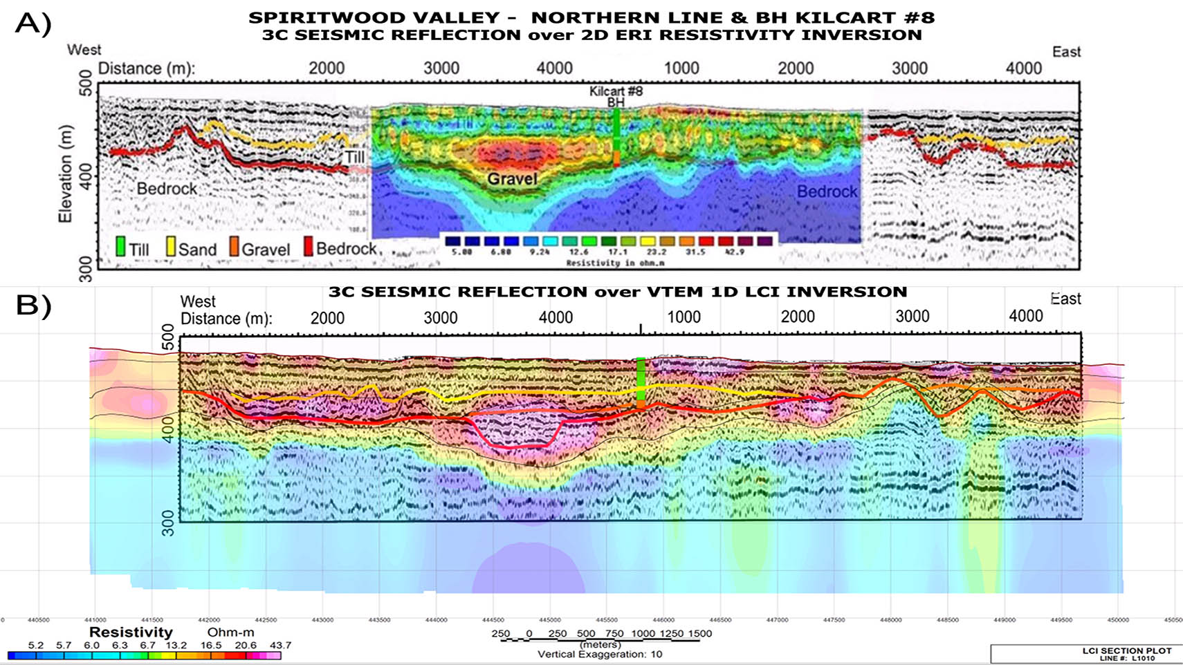
Figure 3a) P-wave seismic section at the north end of the area, overlain with the surface electrical resistivity inverted data. 3b) VTEM™ LCI inversion section overlain with seismic section; 3c) S-wave seismic section from the central part of the area, with interpreted sand and gravel aquifer channels;
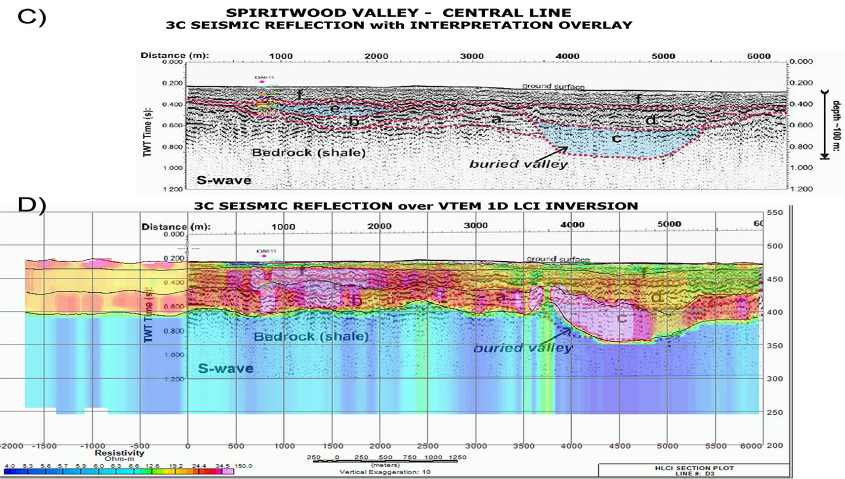
Figure 3c) S-wave seismic section from the central part of the area, with interpreted sand and gravel aquifer channels; 3d) Combined VTEM LCI inversion and seismic data. Initial model for the inversion consists of 3 layers plus basement (thin black lines are inverted borders – seismic and ERI data from Oldenborger et al., 2011).