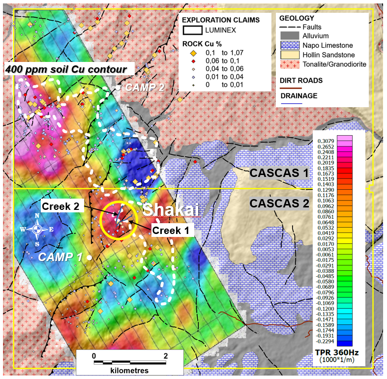
|
![Download VTEM brochure [ PDF - 3.2 Mb ] Download VTEM brochure [ PDF - 3.2 Mb ]](http://geotech.ca/images/stories/vtem/vtem031208_HR-1.jpg) Download VTEM brochure [ PDF - 3.2 Mb ]
Geotech’s award winning VTEM system has the highest signal to noise ratio of any airborne EM system resulting in the deepest possible depth of investigation. VTEM also has the best conductance discrimination for high conductance targets due to its standard base frequency of 30 Hz, long on-pulse, and derived B-Field. The receiver is a very low noise coil allowing for minimal spatial filtering resulting in excellent spatial resolution.
Features
- In-loop transmitter – receiver geometry to provide a symmetric response to allow for intuitive conductor interpretation.
- Low noise receiver and in-loop transmitter – receiver geometry provides for high spatial resolution.
- Low base operating frequency – standard is 30 or 25 Hz time base operation in countries with 60 or 50 Hz power lines.
- Long on – pulse and B-Field data to detect and resolve high conductance targets.
- Large dipole moment transmitter to penetrate through conductive overburden.
- Easily deployable to all parts of the world.
Benefits
VTEM is the dominate time-domain electromagnetic system in the world. As of February 2008, 20 systems were flying worldwide. VTEM has the largest transmitter loop in the airborne industry. The coincident, vertical dipole transmitter – receiver configuration provides a symmetric system response. Any asymmetry in the measured EM profile is due to conductor dip, not the system, or direction of flying. This allows for easy identification of the conductor location and for interpretation of the EM data. The low noise receiver, plus the high power transmitter yields a system that has the best signal to noise ratio of any airborne system.
VTEM has been designed to detect and discriminate between moderate to excellent conductors using a low base frequency, long pulse width, and derived B-Field. The B-Field is derived from integrating data collected at 96 kHz over the entire waveform.
The system is easily disassembled into small enough pieces to be shipped using standard containers. Geotech maintains an inventory of spare parts to ensure the system can be repaired easily in the field.
Specifications
Transmitter
| Transmitter – receiver geometry |
Inloop, vertical dipole |
| Transmitter coil |
Dodecagon shape – vertical axis, 540 m2 |
| Base frequency |
Standard 30 or 25 Hertz depending on powerline frequency |
| Pulse shape |
Polygonal (see waveform) |
| Pulse width |
Typically 43% of the half cycle – over 7 ms in length |
| Peak dipole moment |
Up to 625,000 NIA (400,000 typical) |
| Peak current |
Up to 310 Amperes (200 typical) |
Receiver
| Coil |
Air-core loop, vertical dipole |
| Sample rate |
96 kHz over entire waveform |
| Bandwidth |
Up to 50 kHz |
| Spheric noise rejection |
Digital |
| Industrial noise rejection |
60 or 50 Hz |
Mechanical
| Nominal survey speed |
90 km/hr |
| EM transmitter/receiver ground clearance |
30 meters |
| Operating temperature |
-45° C to 45° C |
| Power requirements |
From helicopter, auxiliary power not required |
| Shipping |
Standard packaging (longest piece – 2.5 metres) |
| Installation/Assembly time |
One day typically |
 An example of VTEM dB/dt and B-Field data is shown. It can be seen that the B-Field data responds to the better conductors and that the overburden response is suppressed. This is allows for easier interpretation of bedrock EM anomalies. The high signal-to-noise ratio of the system is also readily seen in the data.
Waveform
Geotech uses a complicated waveform which has been optimized to use as much of the helicopter’s spare electrical power as possible. Depending on the requirement of the survey, the pulse width can be modified – i.e lengthened, or shortened, or simplified. For a known transmitter – receiver geometry, the dB/dt seen in the receiver is proportional to the current in the transmitter. The current waveform in the transmitter is obtained by integrating the dB/dt receiver coil response and then scaling to the maximum current. A typical receiver measured waveform and the derived pulse shape is shown:
 |